Here are the simulations of the baxandall tone control part. The first picture shows how the low frequency amplitude changes after passing through the tone control when the pot is turned to max and min bass :)
And here you can see what happens when you twist the treble pot.
Note: The frequency range in there pictures is logarithmic (Means the range is increasing with acceleration). So it may seam that the bass pot is effecting a wider range, but it is not.
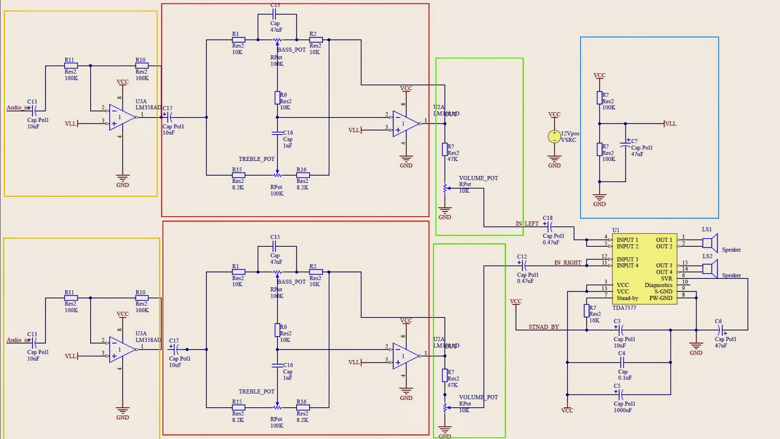
Now for more detailed explanation, here is the same, but divided circuit:
YELLOW - this part helps the audio signal to get in the circuit. Mostly because of the impedance differences. The resistors values should be higher than 10K. This part is not necessary and has a con because it may bring more noise into the audio signal.
RED - this is the one and only (well there are actually two of them in the circuit) the baxandall tone control circuit. By adjusting the pots you can change the low or high frequency amplitude, it works like an adjustable filter. And another thing about this part is that I have made an ACTIVE baxandall tone control, which means that this part requires a power source, but for that the passing signal doesn't lose strength. You can make a passive one by just removing the op-amp at the end of the red block circuit, but then it will lose about 20dB of signal power.
GREEN - this part is the volume adjustment, you can simply put a pot here. But you can also add a resistor just before it, it will limit the max available (so the speakers wouldn't blow out and sound clear at maximum volume).
BLUE - this part is required if you are feeding this circuit with a single polarity power source, which means for example +12 and GND. This sets a level at the op-amps non-inverting input. Otherwise and actually even better if your feeding the whole circuit with a bipolar power source (+12, -12, GND). To do this all the op-amps will use +12, -12 as power source only the amp will still be running on +12, GND (mainly because TDA7377 operating power limit is 18V, so if you will give it +12 and -12 (sum is 24V) you will probably burn it). If the power source is bipolar all the non-inverting op-amp inputs should be grounded.
And what is left is the amp itself, the circuit is from its datasheet. If you do not need (or do not want the awesome baxandall tone control) you can apply the audio signal straight to the ports "IN LEFT" and "IN RIGHT" :)
Now just to build a box for this project and it will be completed :)


No comments:
Post a Comment